Project
From section 1.2 of the Project Plan:
There are situations in our lives that require light. The purpose behind the Flying Flashlight is to provide a portable lighting system that allows a hands-free experience while providing uninterrupted lighting for an extended period of time.
Possible scenarios include nighttime roadside emergencies. A person may need both hands free to change a tire rather than hold a flashlight. The Flying Flashlight also serves to alert other drivers on the road to the person’s whereabouts, creating a safer environment for the time the driver spends outside of the vehicle.
Law enforcement could deploy our product instead of using road flares. Road flares pose fire and safety hazards, especially in dry climates. Road flares also burn for a finite period of time. Flying Flashlight is provided with a battery that far outlasts the burn time of a single flare.
Lighting for backyard activities. Parents can deploy the Flying Flashlight when their children are playing in the backyard where power for lighting may not be available. Light allows children to see and play safely during the twilight hours. Flying Flashlight can even be used for backyard barbecues or any yard activity requiring light where power is not readily available.
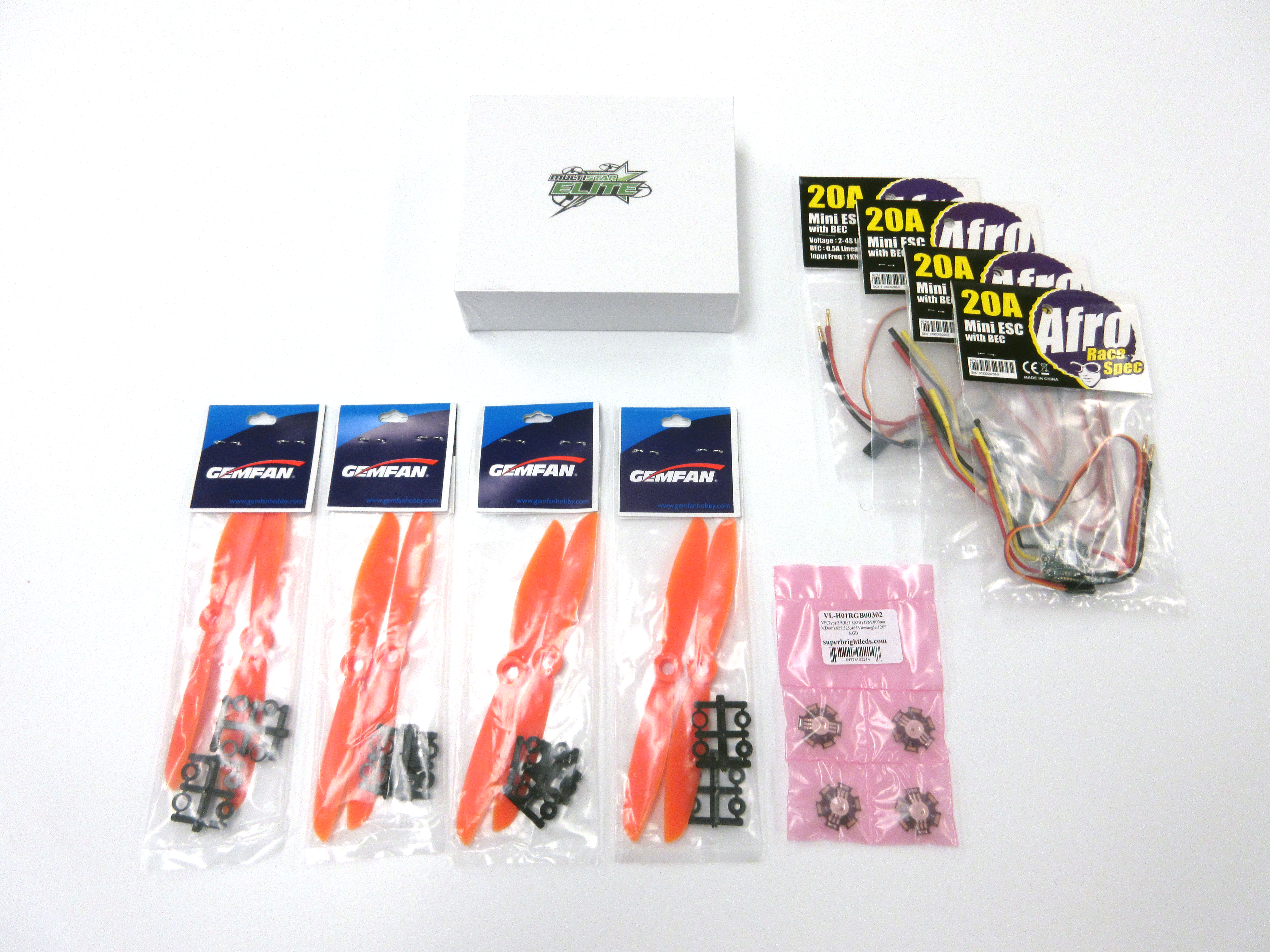
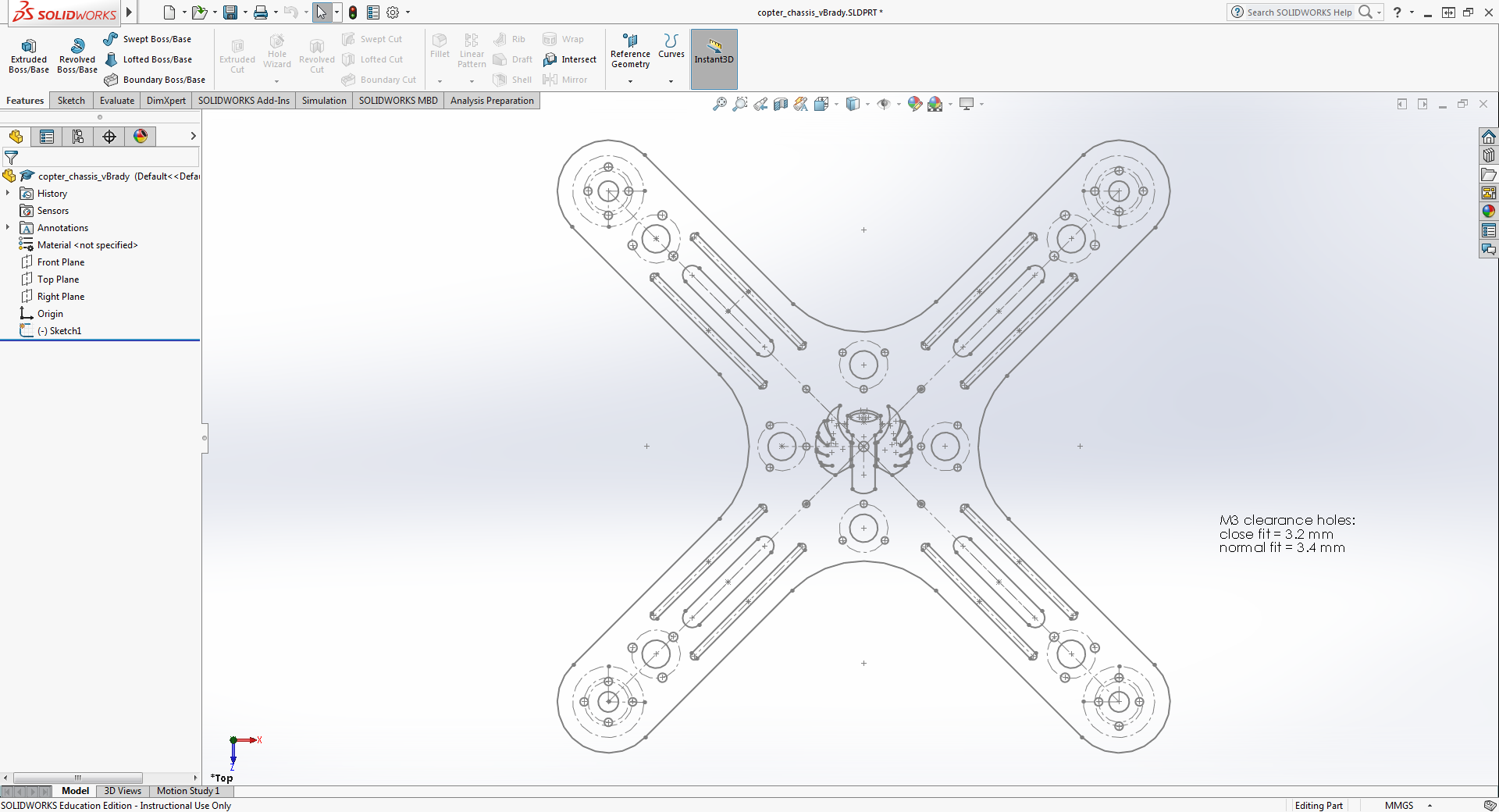
Parts for the project arrived the week of Oct. 24. CAD drawings of each of the parts were created the following week, and a frame was designed and laser-cut from an acrylic sheet. CAD files for each of the components can be found on the Documents page. Code implementation and testing begins the week of Nov. 7, at which point the group will evaluate the current design of the frame, and decide if the design will be sufficient. Potential changes to the design may include change of material thickness or color, change of weight reduction cuts, and change of hole positioning for the parts.
During the week of Nov. 7 and Nov. 14, the team began testing code implementation and basic drone control. Initial testing was performed using a pair of Arduino Uno units, XBee wireless tranceivers, and a joystick. Code for the project was developed using the Arduino development environment using C as the programming language. On the final version of the Flying Flashlight, a PCB will be designed for each end of the system (receiver and transmitter) each communicating via XBee or Bluetooth protocol.
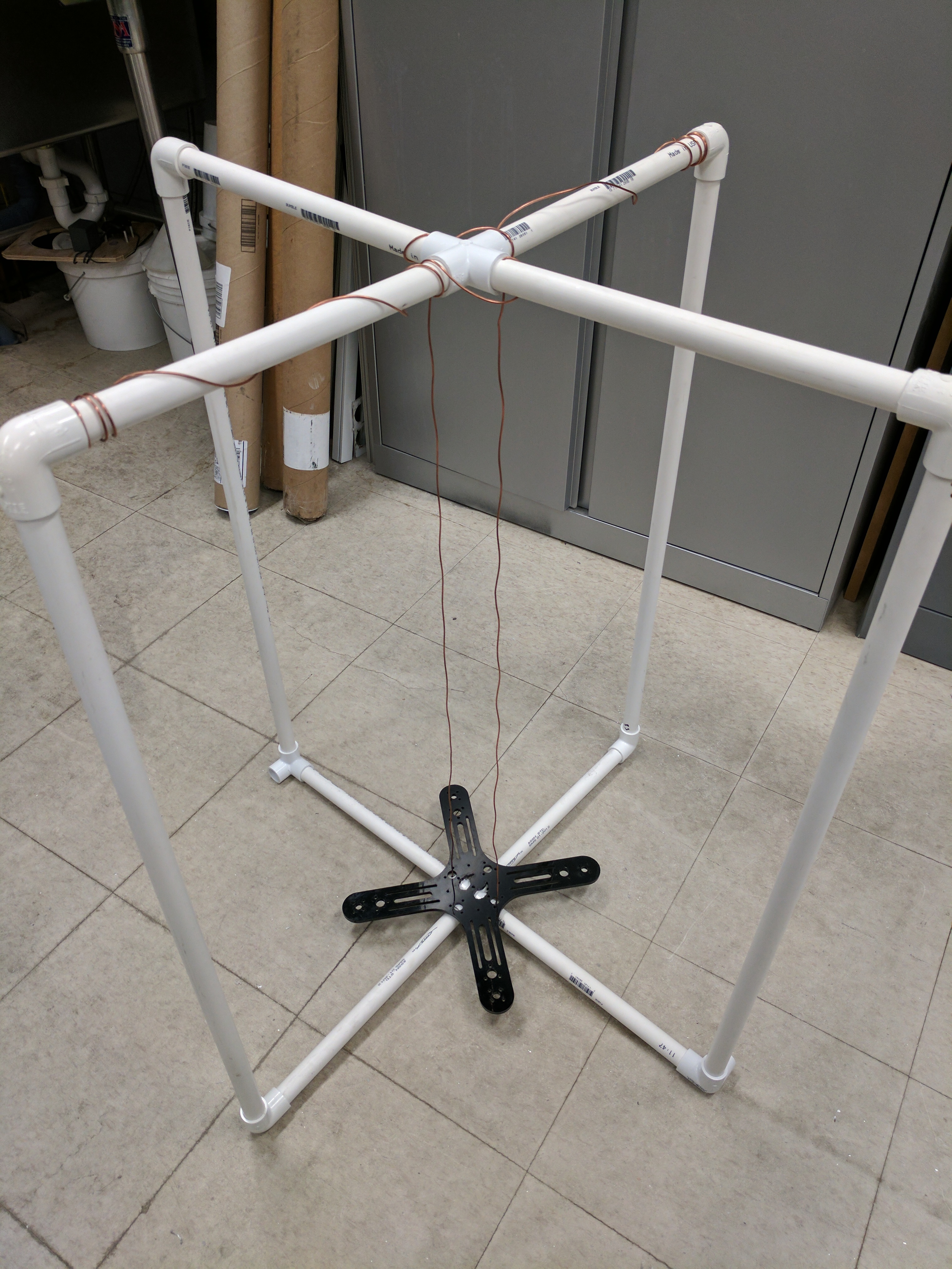
During the week of Nov. 28, a testing aparatus was made using PVC in order to help protect the drone and maintain control as code development continued. The drone rides on a track which keeps it from flying too far off course as the team tests takeoff and hover code. This harness has adjustable height, ranging from three to 8 feet.
Beginning at the end of the Fall semester of 2016, and continuing into the Spring semester of 2017, a PCB was developed in order to provide power to the drone, as well as to communicate with the flight controller.
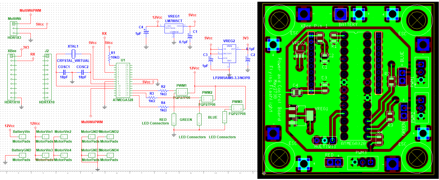
The PCB takes in power from the battery at 12 volts, and distribute the power to the ESC's, which power the motors as well as the flight controller. The board has two power planes, supplying 12v and 5v, which is necessary for the receiving microcontroller. The Multiwii flight controller has the capability of supplying 5v to the receiving microcontroller, but as a backup, we decided to also include a 5v regulator from 12v. From this 5v, we also need to regulate down to 3.3v for our XBee wireless transceiver.
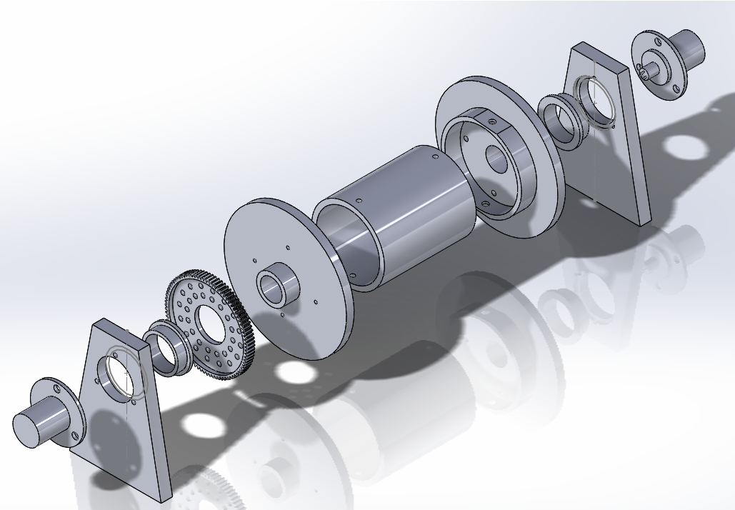
During the PCB design process, and the waiting period for the PCB, the cable drum assembly was developed. Using SolidWorks, a model of a drum system was created to match our needs. The drum uses a pair of slip ring assemblies to provide power from the battery to the rotating drum. A mount plate also began development in order to utilize a drone testing tripod made for CprE 488, which would allow for stability testing in a safe environment.
During testing, a significant level of vibrations in the frame was discovered. These vibrations hindered the ability to tune the PID controller used to stabilize the drone. Due to this, a new frame design was created with the goal of reducing these vibrations. Alternative pre-designed frames were also researched as a backup condition. Upon testing the redesigned frame, vibration issues persisted. As a group, it was decided that in order to eliminate a point of uncertainty the store-bought frame would be used to test flight stability.
Testing continued after assembling the new frame. While vibrations were dampened, the flight controller still was unable to correct its flight path. PID controller tuning did not have the appearance of aiding the stability of the drone.
The LED lighting system was tested during flight testing. The results of this test were very pleasing, as the lighting system was easily able to light a dark room. When operating at full brightness, the LED system drew 1.94 Amps at 12 Volts, and at half brightness it drew 0.95 Amps at 12 Volts.
